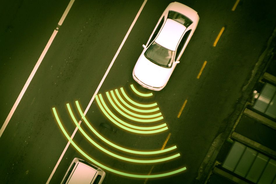

Terahertz imaging, which is already familiar from airport security checkpoints, has a number of other promising applications — from explosives detection to collision avoidance in cars. Like sonar or radar, terahertz imaging produces an image by comparing measurements across an array of sensors. Those arrays have to be very dense, since the distance between sensors is proportional to wavelength.
In the latest issue of IEEE Transactions on Antennas and Propagation, researchers in MIT’s Research Laboratory for Electronics describe a new technique that could reduce the number of sensors required for terahertz or millimeter-wave imaging by a factor of 10, or even 100, making them more practical. The technique could also have implications for the design of new, high-resolution radar and sonar systems.
In a digital camera, the lens focuses the incoming light so that light reflected by a small patch of the visual scene strikes a correspondingly small patch of the sensor array. In lower-frequency imaging systems, by contrast, an incoming wave — whether electromagnetic or, in the case of sonar, acoustic — strikes all of the sensors in the array. The system determines the origin and intensity of the wave by comparing its phase — the alignment of its troughs and crests — when it arrives at each of the sensors.
As long as the distance between sensors is no more than half the wavelength of the incoming wave, that calculation is fairly straightforward, a matter of inverting the sensors’ measurements. But if the sensors are spaced farther than half a wavelength apart, the inversion will yield more than one possible solution. Those solutions will be spaced at regular angles around the sensor array, a phenomenon known as “spatial aliasing.”
Narrowing the field
In most applications of lower-frequency imaging, however, any given circumference around the detector is usually sparsely populated. That’s the phenomenon that the new system exploits.
“Think about a range around you, like five feet,” says Gregory Wornell, the Sumitomo Electric Industries Professor in Engineering in MIT’s Department of Electrical Engineering and Computer Science and a co-author on the new paper. “There’s actually not that much at five feet around you. Or at 10 feet. Different parts of the scene are occupied at those different ranges, but at any given range, it’s pretty sparse. Roughly speaking, the theory goes like this: If, say, 10 percent of the scene at a given range is occupied with objects, then you need only 10 percent of the full array to still be able to achieve full resolution.”
The trick is to determine which 10 percent of the array to keep. Keeping every tenth sensor won’t work: It’s the regularity of the distances between sensors that leads to aliasing. Arbitrarily varying the distances between sensors would solve that problem, but it would also make inverting the sensors’ measurements — calculating the wave’s source and intensity— prohibitively complicated.
Regular irregularity
So Wornell and his co-authors — James Krieger, a former student of Wornell’s who is now at MIT’s Lincoln Laboratory, and Yuval Kochman, a former postdoc who is now an assistant professor at the Hebrew University of Jerusalem — instead prescribe a detector along which the sensors are distributed in pairs. The regular spacing between pairs of sensors ensures that the scene reconstruction can be calculated efficiently, but the distance from each sensor to the next remains irregular.
The researchers also developed an algorithm that determines the optimal pattern for the sensors’ distribution. In essence, the algorithm maximizes the number of different distances between arbitrary pairs of sensors.
With his new colleagues at Lincoln Lab, Krieger has performed experiments at radar frequencies using a one-dimensional array of sensors deployed in a parking lot, which verified the predictions of the theory. Moreover, Wornell’s description of the sparsity assumptions of the theory — 10 percent occupation at a given distance means one-tenth the sensors — applies to one-dimensional arrays. Many applications — such as submarines’ sonar systems — instead use two-dimensional arrays, and in that case, the savings compound: One-tenth the sensors in each of two dimensions translates to one-hundredth the sensors in the complete array.
James Preisig, a researcher at the Woods Hole Oceanographic Institution and principal at JP Analytics, says that he’s most interested in the new technique’s ability to reduce the computational burden of high-resolution sonar imaging. “This technique helps significantly with the computational complexity of using signals from very large arrays,” Preisig says. “I can imagine it being deployed in situations where you are using very, very large arrays to get good spatial resolution, but you’re processing signals on a vehicle or something where you did not have significant computational power.”
In those contexts, Preisig says, the new technique’s sparsity assumptions make perfect sense. “In this context, the field of view is divided into sectors,” Preisig says.
“The field has to be sector-sparse — only a subset of sectors have objects in them. That is realistic.”


